Informative Links
- Test Fixture and MEMS Test Fixture Design
- Circuit Design
- Semiconductor Fab Equipment Design
- Instrument Design for the Chemical, Biotech and Life Sciences Industry
Portfolio of
Example Projects
8 Site Angular MEMS Accelerometer Test Fixture Project
Shown below are some pictures of components for a multi-site production test fixture we designed for testing angular MEMS accelerometers. This fixture was designed from the ground up. When viewing the pictures keep in mind that for any inertial test fixture, including this one, one of the most important design goals is maximizing the modulus to density ratio of the fixture. What this means is that you are trying to maximize the mechanical stiffness while at the same time trying to keep the fixture as light as possible. The engineer must use his PCB design skills to make the smallest pc board possible while also properly working with the mechanical design to make sure all the mechanical constraints such as proper DUT clamping, fixture mass, pcb mounting screw sizes and locations are met. These pictures illustrate how useful the value of combined electrical/mechanical skills are when designing such a project.
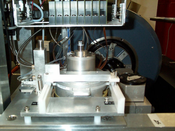
Front view of test fixture. The test fixture is the round cylindrically shaped object in the center. The fixture is mounted on an oil bearing and rotates. The shaker, whose armature can be seen in the back, provides the stimulus to the fixture.
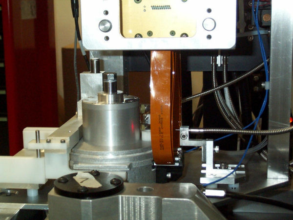
Side view of the fixture showing the flex cables which provide all electrical connections to the fixture.
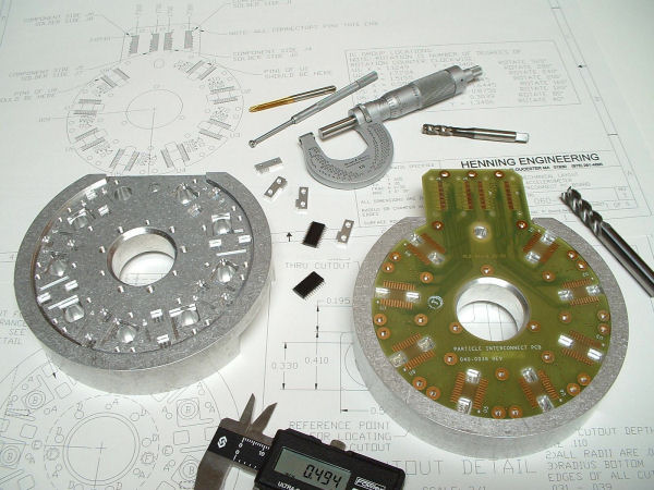
Base of test fixture on left and base with contactor board installed. The DUTs are the SO package ICs shown in the center. The fixture provides electrical contact to the DUTs via the contactor PCB shown on the right. Since this is a fixture for angular accelerometers the parts are situated in a radial pattern.
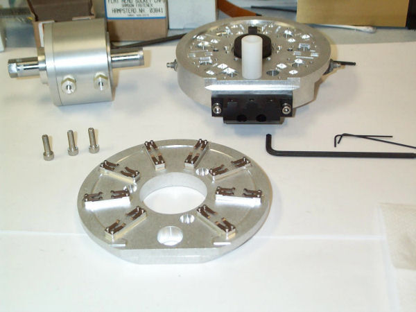
Top clamp plate, base and pneumatic clamping cylinder shown before assembly.
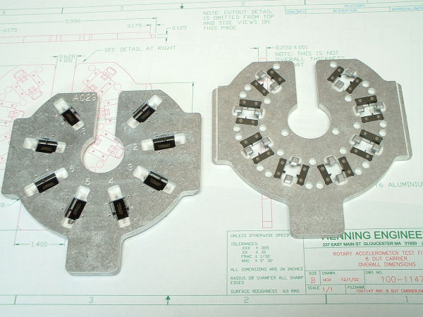
Top and bottom view of the carrier that holds the DUTs in place on the contactor. Top view on left has MEMS accelerometers in place.
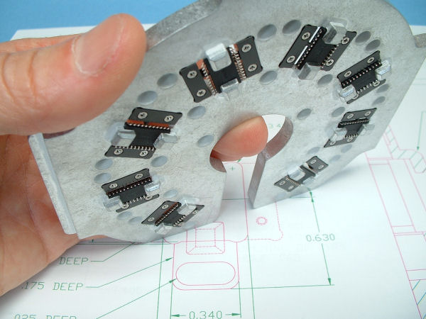
Close up view of bottom of carrier. DUTs are in place and their leads can be seen.
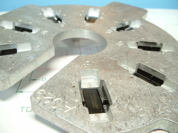
Close up view of top of carrier.
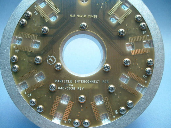
Top view of contactor board.
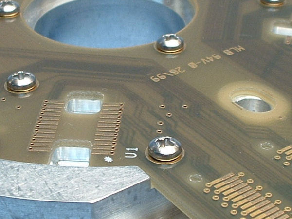
Close up of contactor board and base. Fit and design of mechanical and electrical components is seamless.